multiMap Shading Network
This is an old article from the end of 2006. Since I’m closing the site it was on ’till today, I’ve decided to add it as a backdated post here.
Chapter I. Basics description
Chapter II. Example of assigning color maps
Chapter III. Example of assigning displacement maps
Chapter IV. Final notes
Chapter I. Basics description
Fundamental idea is to assign separate textures to specific parts of a whole mesh. For example, we have a character – one-piece mesh – and we want to assign big separate displacement map to his face, a smaller one – to the head, another one to the torso, arms, legs… Or maybe assign separate 4k displacement map for the lips, if they are intended for close-up.
How to approach this – there’s a number of different ways, but almost all of them for some reasons turn out to be irrelevant. The best method I’ve found is to cut out mapping shells of needed regions, stretch them to the whole UV quadrant and offset in +U direction – that means not to put all of them in standard 0-1 UV quadrant, but in neighbouring ones also:

Such applications as zBrush and Mudbox allow sculpting details/deformations and generate separate displacement maps for each mapped UV quadrant:

And as a result there’s no need to suffer from the lack of texture space in 4k map for wrinkles on the character’s lips. But the new question arises – how to apply this technique further 🙂
Once again, there’s a number of methods, but every single one has specific disadvantages of different severity. Purpose of the my script is to perform the best solution for assigning such textures to the meshes with such mappings in Maya.
I’ll explain everything with two direct examples.
Chapter II. Example of assigning color maps
Target: to texture a one-piece model of corridor with separate textures, seamless and with custom placement of elements. Corridor is for the movie, so height of the texture should be around 1556 pixels. Rounding it up ’till next “texture” resolution – 2048. Corridor is 10 times as long. That means that texture should be 20480×2048 🙂 Obviously, that’d be a problem to do. We can separate a corridor in a number of sections, but then we’ll need to deal with a bunch of shaders and some artifacts on seams. Something different could be tried also, but I suggest the method mentioned above as the best.
1. We have a wall of our corridor (super hi-rez :))
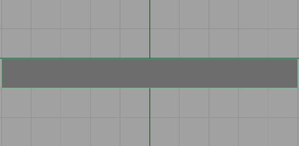
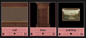
2. And we want to place these textures so that “wall” would tile along the whole model, “door” and “painting” would be placed above it by their alpha channels:
3. We need to map it proportionally as mentioned above – since height is 0-1 in V, width would be 0-10 in U – 10 UV quadrants in +U direction:

4. Now we run MEL command:
multiMap;to get the script’s GUI (it’s written by Denis ‘0-1’ Rybakov)

5. Cells on the top represent 10 UV quadrants – from 0 to +10 in U (these values are fixed for script’s simplification, so you need to place your uv shells only in them). We need to place our textures in these cells. The left-most texture would be automatically tiled, others would be placed above. So, we select texture node we need and click on the appropriate cell – swatch of out texture will appear. That way we compose out corridor (if you press “Clear all” – all cells would become empty)

6. Select object and press GO!!! The first thing script will do is scaling the whole mapping of this object to 1/10 pivoting in 0x0

7. If mapping was done as explained above – in 0-10 +U quadrants, it’d fit exactly into corresponding boxes in the lowest row of standard 0-1 quadrant:

8. Then shading network will be created. The left-most texture (wall) is the bottom tiled layer and the rest of them (door and painting) are layered above in appropriate locations. Composition of layers is handled by layeredShader in “layeredTexture” mode (standard layeredTexture doesn’t preserve float point data – 32-bit displacement maps couldn’t be composed with it – but layeredShader does – that’s the reason of it’s usage). Placements are created also with their attributes modified is such a way, that textures fit into appropriate boxes of mapping. If one texture is selected more than once – script would make a duplicate:
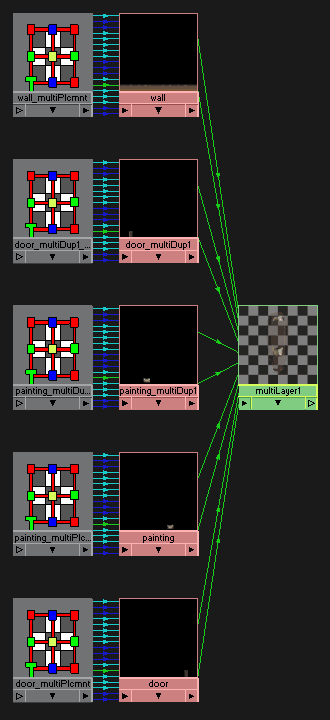
9. Resulted layeredShader (multiLayer1 – it’s actually a shader, but will be listed in Textures section of hypershade) could be assigned to needed channel of main shader and rendered:

10. Let’s say, we don’t like the placement of the elements – we can just replace swatches in GUI of the script (if we deselect everything and click the cell with a swatch in it – it’d be emptied)

11. …and press GO!!! again – network will be automatically remade – all output connections of multiLayer1 will be preserved for the new layeredShader. That’s a pity – I’ve found no way to maintain full-scale swatches for textures modified earlier (after placements they’re just black boxes with a tiny texture at the bottom) – no way to solve this without unnecessary nodes – so, you can replace cells orienting by names, or you can press “Delete latest multiMap network” first – it’ll completely decompose previous network and return swatches in their full scale (but multiLayer’s connections wouldn’t be preserver, of course)

12. Modifications of specific elements could be made in standard way by hand – via attributes of placement nodes. For example, we want to scale down one of the doors and magnify one of the paintings:

That way we can map up to 10 different textures. If you need to, you can create two networks with 10 textures each and combine them in another layeredShader.
Chapter III. Example of assigning displacement maps
1. Actually, the method is the same. We have a simple plane:
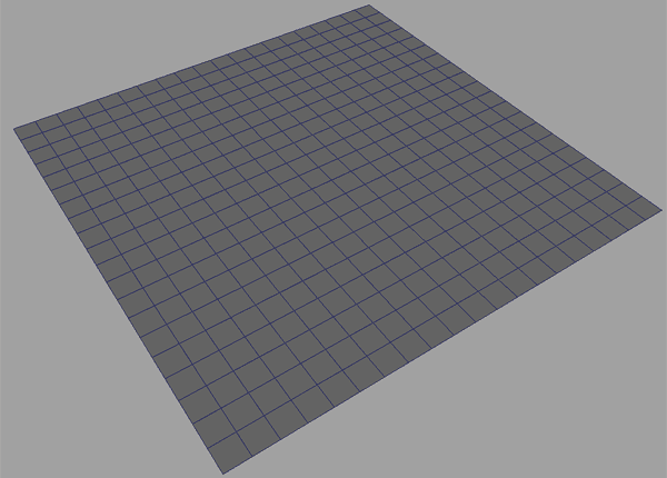
2. With multiMapping into 6 UV quadrants:

3. In zBrush we make some sculpting and generate displacement maps for each UV quadrant:
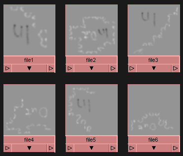
4. Rum multiMap script and place maps into corresponding cells:

5. Select the plane, press GO!!! Script scales mapping down to 1/10:

6. and fits them into corresponding 6 boxes of the lowest row of standard 0-1 UV quadrant:

7. The difference in assignment of displacement maps is that we need to deactivate tiling of the left-most texture. This could be done manually in it’s placement node:
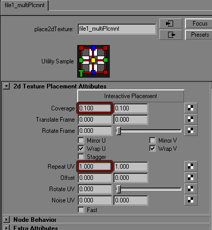
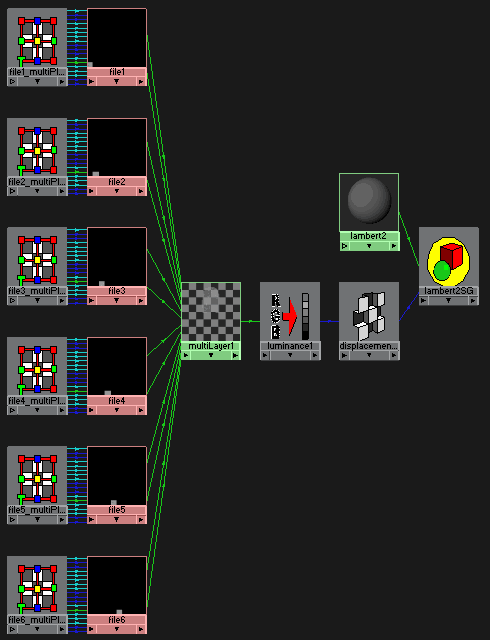
8. Resulted multiLayer1 could be plugged into “luminance” node and assigned as a displacement to main shader:
9. Rendered plane:
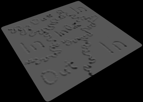
Purposely I’ve painted wiggly lines right on the seams – to see whether seamless result is achieved. Everything is good, as you can see – 6 displacement maps connect to each other seamlessly (that’s an achievement in zBrush options also). The artifact at the lower right is from open edges smoothed in zBrush – doesn’t count 🙂
Chapter IV. Final notes
Also network could be created for mapping that isn’t scaled to 1/10, but it needs a lot of additional nodes. That’s the example if the same corridor wall made for non-scaled mapping:
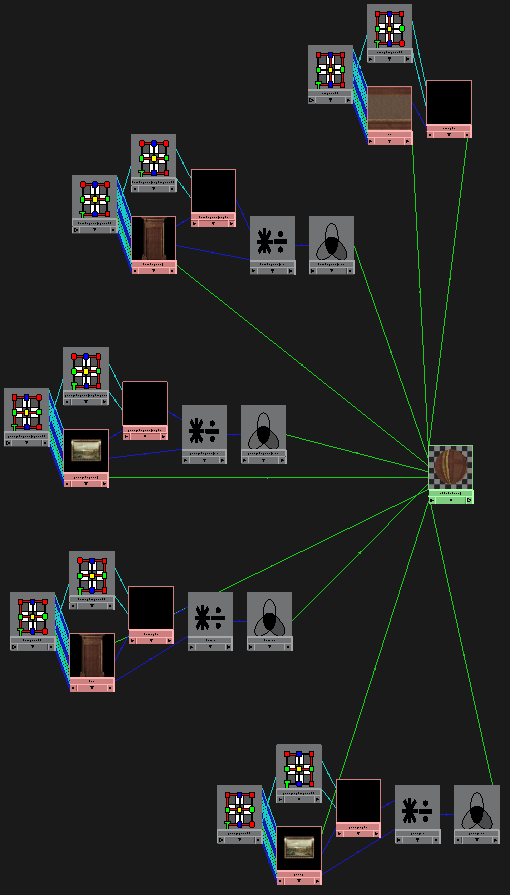
[+] no modifications of object at all, mapping remains original
[+] swatches always remain full scaled 🙂
[-] a lot of additional nodes (mainly for correct layering of textures be their alphas) – big networks
Anyway, adding version of the script that makes this kind of networks – download
In: Render · Tagged with: alpha, displacement, float point, layeredShader, layeredTexture, mapping, maya, mentalray, mudbox, multiDisplacement, multiMap, script, shading, texture, uv, zBrush
